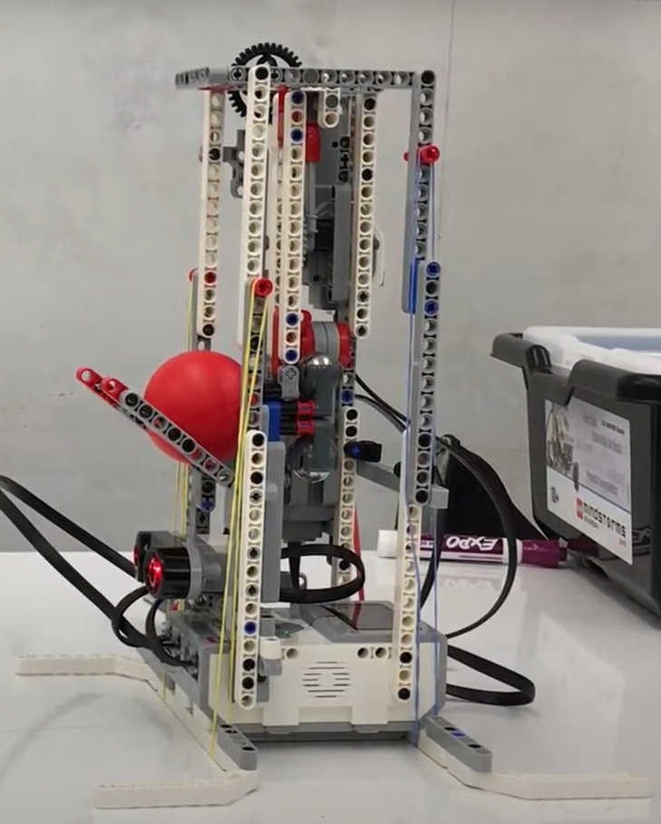
ball thrower

For this project, we were tasked with creating a robot that shoots a ball into a cup. The robot went through two main design iterations. The first robot used a motor to push the ball forward. The angle of release could also be adjusted to give the ball a higher arc. Ultimately, however, this design was not very successful in getting the ball into the cup, so I drastically changed the design. The second robot used a pendulum and trigger mechanism to shoot the ball. A weighted pendulum would be brought to a certain height so that at the bottom of its swing, the velocity would be enough to propel the ball went into the cup. A clutch Lego piece was used for the trigger mechanism. When the clutch was engaged, the pendulum could be held at a high potential energy and when released, the pendulum would swing down and collide with the ball. One major downside to this design is its lack of reliability. The clutch piece, while useful, had a substantial amount of slop before it engaged which can lead to the motor moving but the pendulum arm remaining still. This often caused the robot to undershoot the target. If given more time, this problem could be solved using another distance sensor or sensing the load on the motor to detect when the motor is moving the pendulum. The robot was also controlled remotely via communication with the cloud service SystemLink where one could control the setup parameters of the robot and see the outputs of the sensors.
Two models were used to determine the angle of release for the pendulum: a complex physics model and a linear regression model using gradient descent. The physics model used the trajectory equation to determine the initial velocity the ball needed in order to reach the center of the cup using the geometry of the robot as initial conditions. The velocity of the pendulum was then determined using conservation of momentum assuming a coefficient of restitution of 0.9. Once the necessary velocity of the pendulum was found, the potential energy required to reach that velocity was calculated and the angle of release of the pendulum could be solved for from there.
The second model was a data driven model that used a linear regression of the data. First, 50 data points were taken at different distances and angles. Because the relationship between the angle of release and distance traveled was not linear, the angle values were squared to get a linear fit. Then the slope and y intercept of the regression were iterated through minimizing the R Squared value of the regression. To further increase the accuracy of the model, an optimization was applied to the parameters of the linear regressions (learning rate, number of iterations). Ultimately, however, this approach was not successful in creating an accurate model of the system, so the linear fit of the data in Excel was used for the final model.
The results of the models show that overall, the data-driven approach was more accurate with an average accuracy of 67.5%, while the physics model had an accuracy of only 37.5%. In general, both models were most accurate in a range of between 20-30 cm. Interestingly, the physics model had a 0% accuracy between 30-40 cm while the data driven model had 80% accuracy in that range. Both models struggled at very close range, often overshooting the target. There was an attempt to mitigate this by scaling the result of the models, but the scaling decreased accuracy at longer distances.